- CFD
- →
- Mold CNC
- →
- Prepreg Layup
- →
- Oven Cure
- →
- Mounting
- →
- Competition
- Team
- Four engineers · Advisor Athan Cosse
- My role
- Fabrication and manufacturing lead
- Budget
- $1,750 allocated · ~$3,550 scope, closed by donated materials
- Result
- Passed tech, ran the full FSAE Michigan event
The Problem
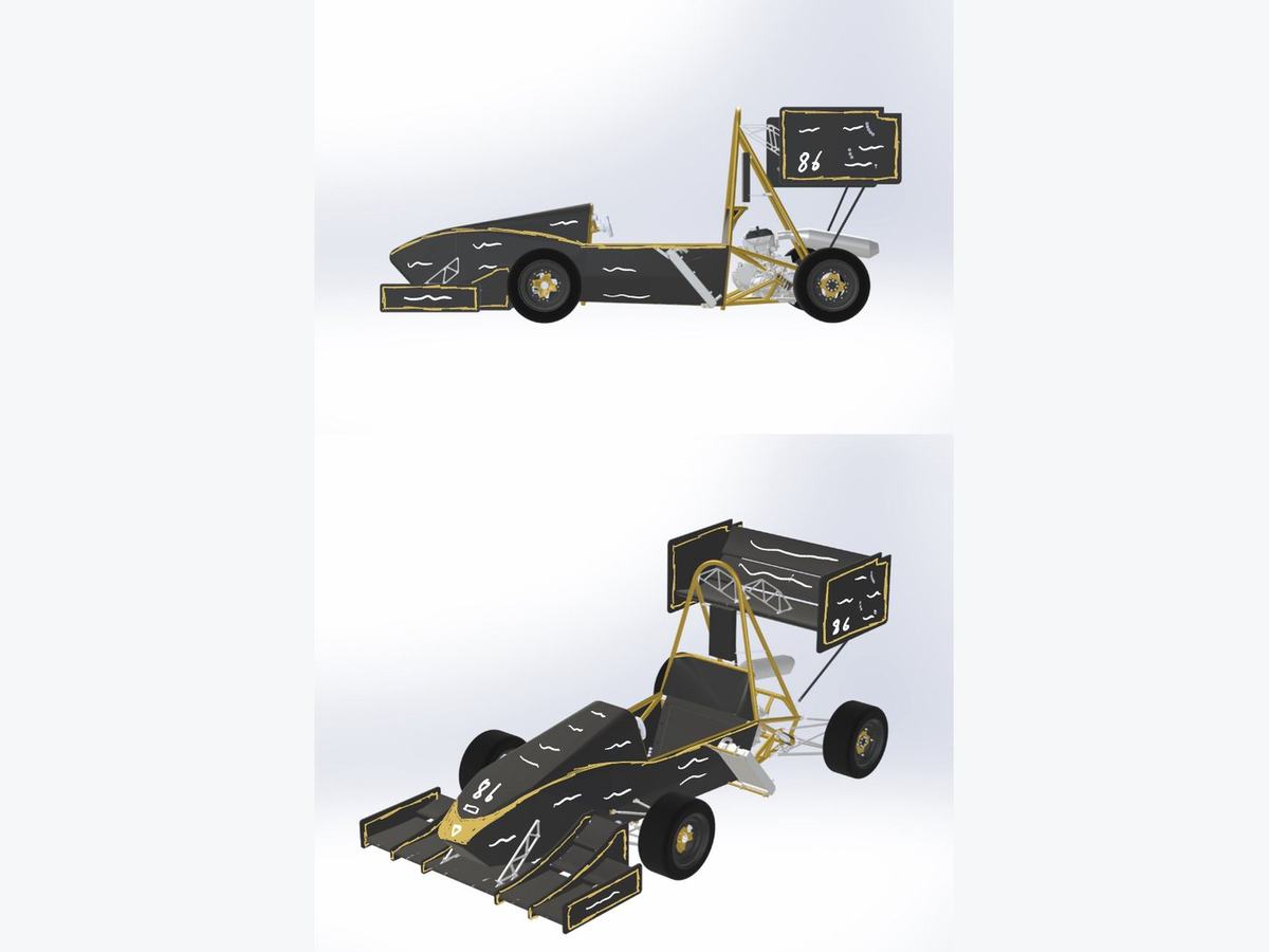
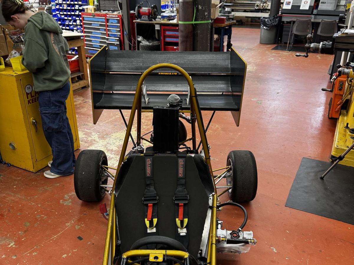
The team wanted lap time in the dynamic events — skidpad, autocross, and endurance — and had no aerodynamic devices at all. More downforce means more tire grip, but every pound of downforce costs drag and mass, and a first-year package that fails tech inspection is worth nothing. So the target wasn't maximum downforce. It was the best downforce-per-pound we could build twice, legally, with the shop we had.
Design was bounded by the 2025 FSAE Rules section T7 and the Structural Equivalency Spreadsheet: no powered downforce devices, aero elements confined to defined boxes relative to the car, minimum radii on any surface a person could contact, mounts that support full load without oscillation, and hand calculations backing every simulation on chassis-mounted hardware. Judges' guidance for a first-year kit was blunt and shaped the whole approach — simplicity, cost, production time, rigidity, and adjustability over complexity.
| Metric | Target | Acceptable | Units |
|---|---|---|---|
| Total package weight | 15 | 20 | lb |
| Center of pressure behind CG | 2.5 | — | in |
| Front wing Cl/Cd | >4 | >3 | — |
| Rear wing Cl/Cd | 4 | >3 | — |
| Downforce per pound, each wing | >5 | >4 | — |
| Deflection at 45 lb | <20 | <25 | mm |
| Permanent deflection at 45 lb | <2.5 | <5 | mm |
| Front ground clearance | 1.5 | >1.5 | in |
Airfoil Selection & CFD
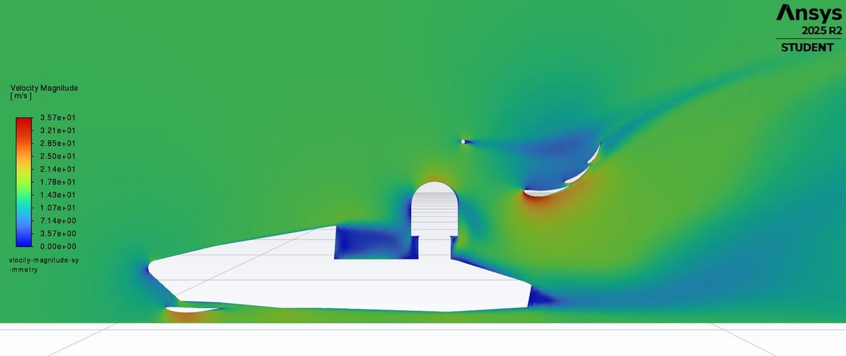
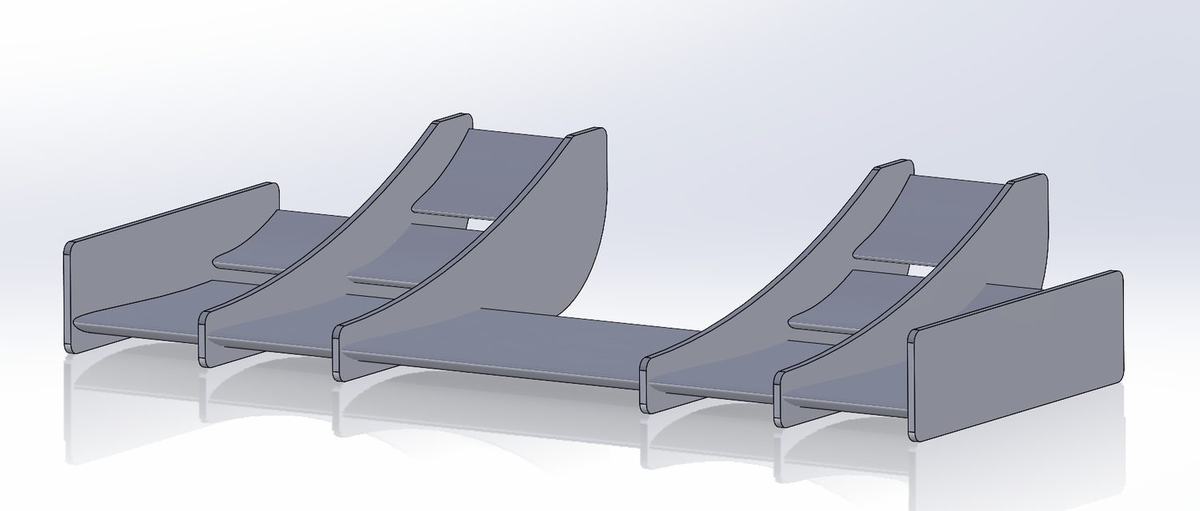
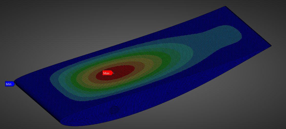
We ran the package on the Eppler 423 high-lift airfoil for the rear wing, and a combination of DAE-51 and E423 up front — the DAE-51 chosen for ground effect with a low drag penalty. Two-dimensional studies in ANSYS Fluent set angle of attack, slot gap spacing, and element overlap, with mesh density increased at the leading edge and through the gap so the pressure field resolved properly. Every run used 15 m/s, the average speed of an FSAE car across the dynamic events.
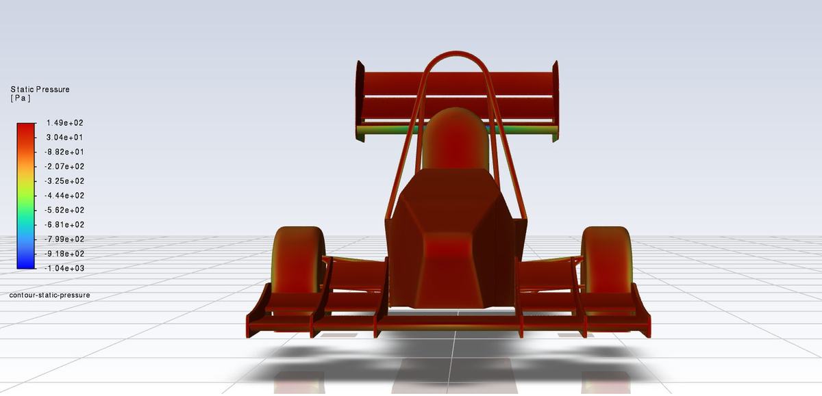
The 2D geometry reached Cl = 4.446 at Cd = 0.184. We then built a simplified model of the car to keep 3D solve times manageable, and it immediately surfaced two problems the 2D work could not have shown.
Air was trapping at the nose and the front wing center. We added a channel at the rear of the front wing to let flow pass under the car. The rear wing wake was separating. Revised spacing and overlap cut the separation and cleaned up the streamlines.
Full-car Cl/Cd came out at 2.23 — lower than the 2D figures, as expected once three-dimensional effects and the rest of the car are in the domain.
Materials & Impact Testing
A front wing on an autocross course gets hit by cones, so skin material was a durability question before it was a weight question. We tested carbon fiber against a denim composite — genuinely cheaper, easier to source, lower environmental footprint, and ductile enough that it might spread impact load rather than concentrate it.
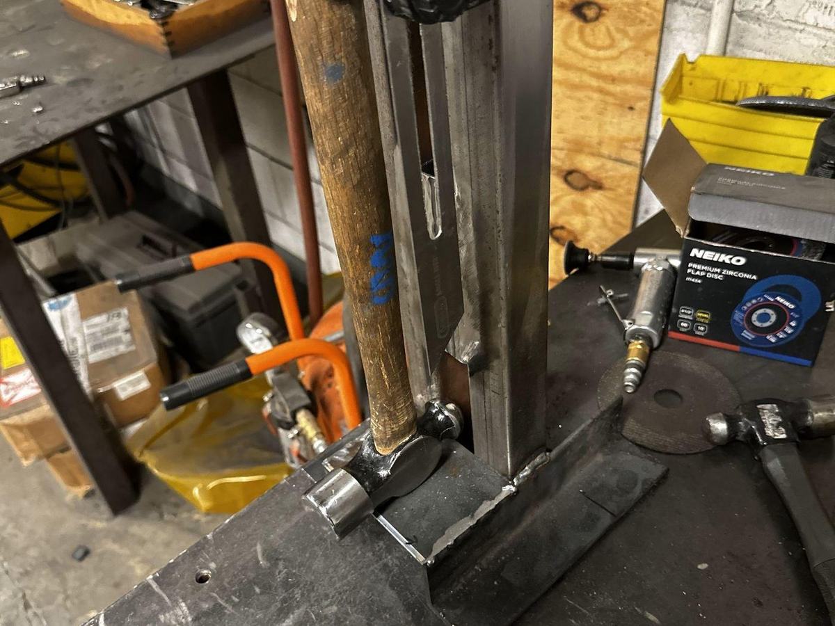
We built a pendulum rig to deliver repeatable strikes: a 1,060 g hammer on a 16-inch arm, released from 90°, about 4.22 J per hit, ten hits per panel with damage recorded after every strike. The method was drawn from the Charpy impact test, though we were explicit that this was a bench comparison for relative material choice, not a certified result.
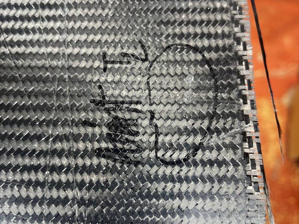
Denim soaked up an enormous amount of epoxy just to wet out, dented in the resin on the first hit, and fractured completely by the tenth. Carbon outperformed it in every case. The best layup for repeated impact was three plies — outer plies at 45°, inner ply at 90° — and that result carried straight into the skin design and the endplate construction.
Tooling & CNC Machining
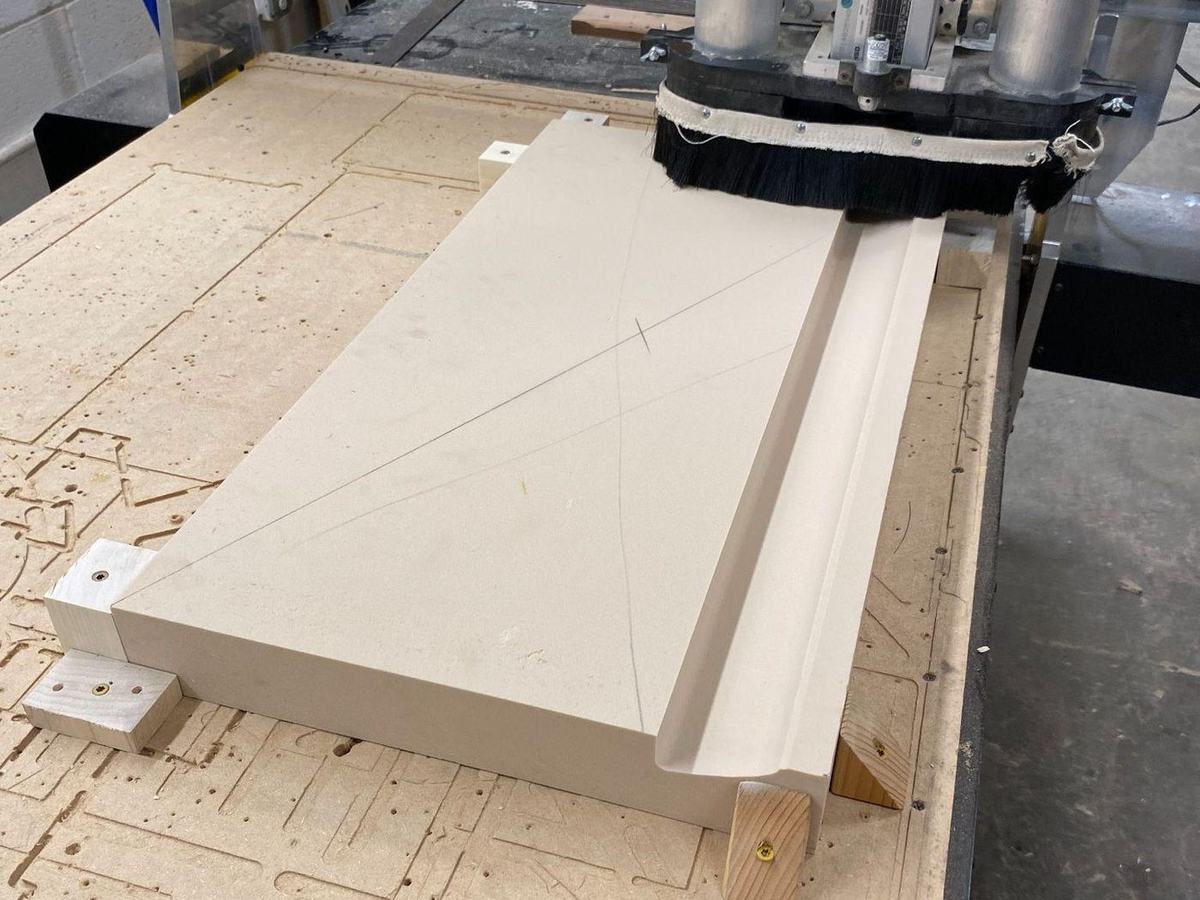
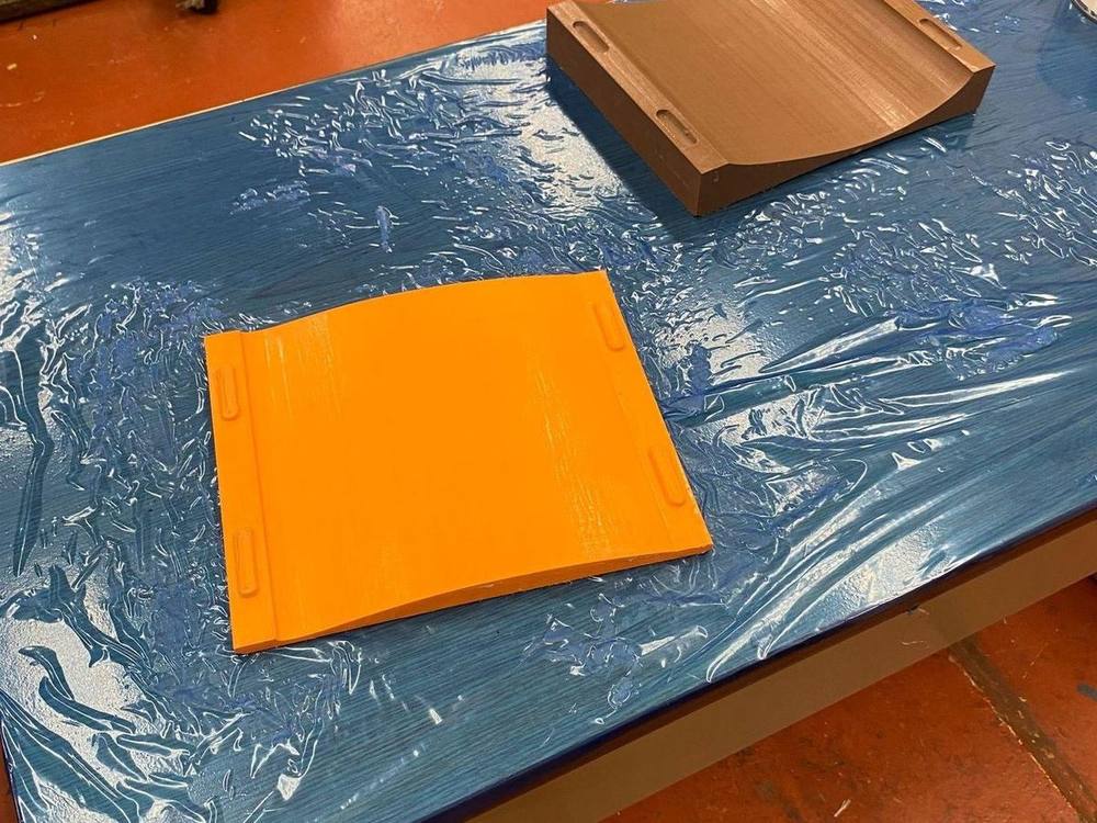
This was my primary responsibility. Early molds were 3D printed, and they failed on two counts: layer lines transferred into the part surface, and heat warped the tools. We moved to high-density tooling foam machined on a CNC router, which meant solving the setup before solving the part.
- The machine table was uneven, so I resurfaced it with a new MDF board to get a flat, trustworthy base.
- I designed a locating jig squared to the cutting arm so the X and Y axes ran parallel to the material, using a fixed corner and locating pins so every foam blank sits identically job to job. Zeroing was a touch-off on the top surface, with extra stock left to absorb small setup error.
- Toolpaths used one large cutter for both clearing and finishing, with feeds and speeds tuned to avoid tearing the foam and keep the edges crisp.
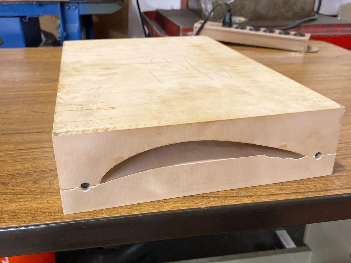
- The front wing is long enough that the top and bottom molds were each cut in two halves — four foam blocks total — joined with steel dowels located by a printed corner jig, with seams filled and sanded flush.
- Finished molds were sanded, sealed with epoxy to close the foam's pores, then treated with two coats of Chemlease mold sealer and four coats of release agent.
The limiting factor turned out to be the post processor. It gave almost no control over the path, so the head decelerated at the end of every pass and never held top speed. A full split mold took a few hours. The fix — writing a Fusion 360 post for the Mountaintop machine — would let the tool exit out the side while slowing, hold speed longer, and control deceleration length directly.
Layup Development
Wet layup trials
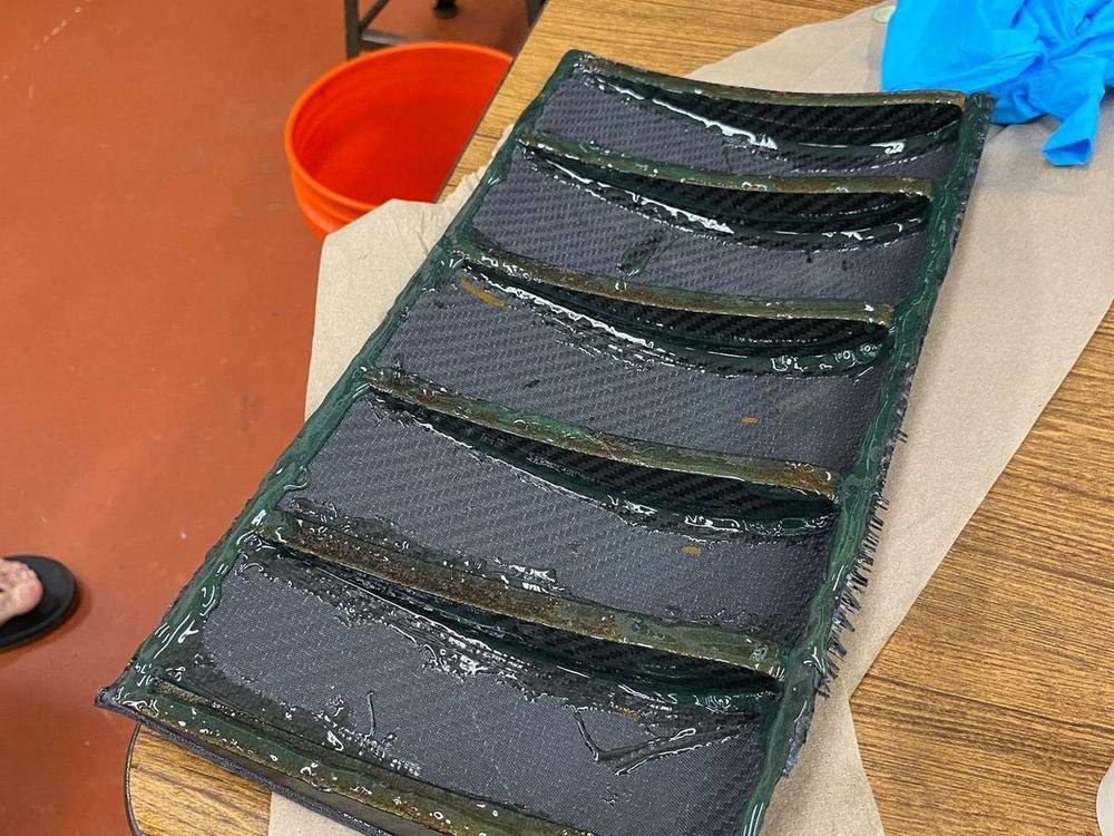
We started with wet layups to learn how the cloth drapes into tight curves and how the molds release. I ran an early full-cross-section trial using a dual-bag "donut" method: one tube bag pressurizing the inner wall of the wing section, a second larger bag enclosing the mold and closing annularly around the first, with release film taped taut and pulled onto the mold geometry by the bag itself. I pulled 30 inHg and held vacuum for six hours.
It worked, and the feedback was more useful than the part. Reviewing it with Bill Maroun, the note was to move the bag seam off the leading edge — the leading edge is the surface that matters most aerodynamically, and a seam there compromises it. Wet layup also showed its own limits: resin content was hard to control, surface finish varied, and repeatability depended too much on who was doing the work.
Switch to prepreg
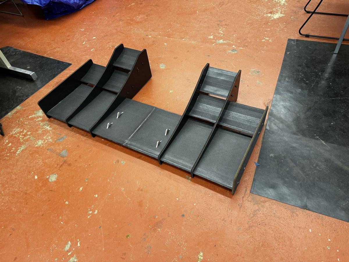
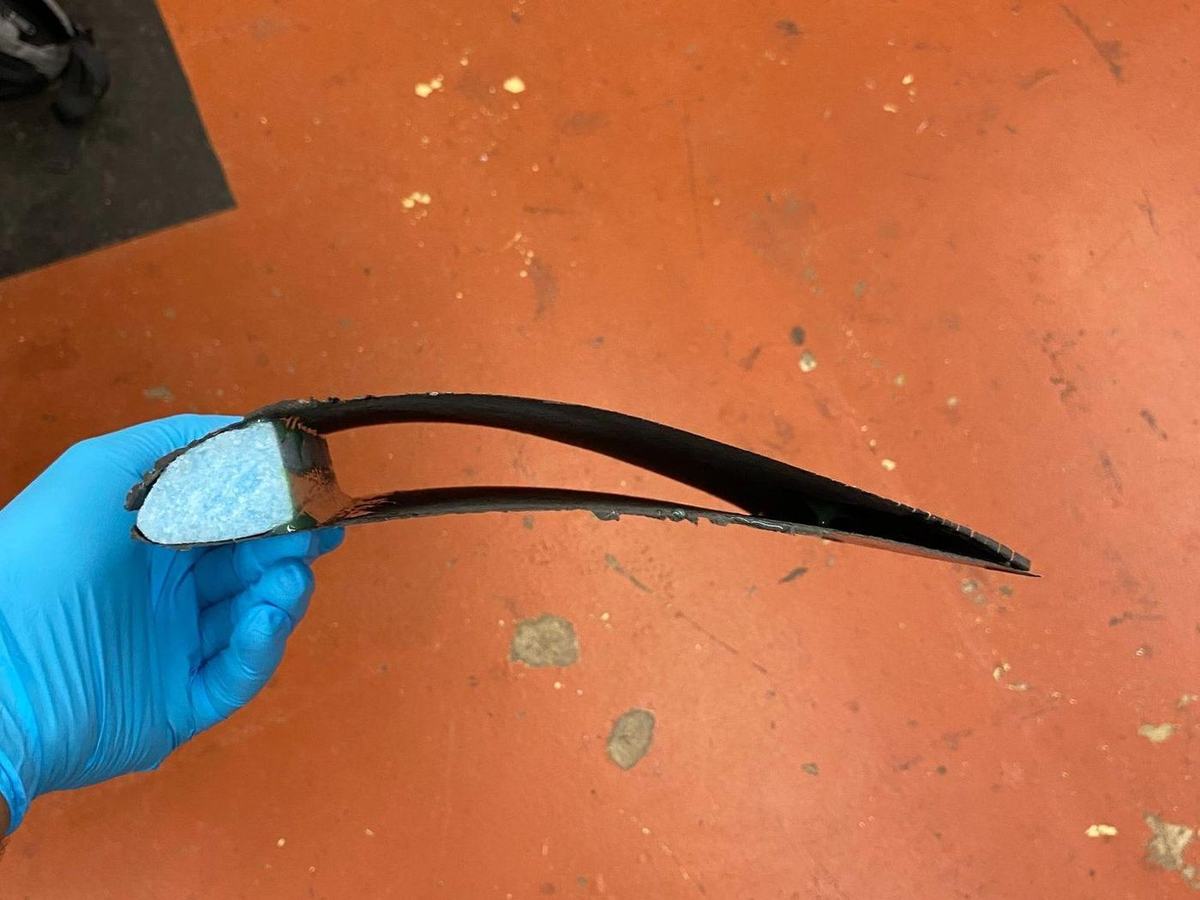
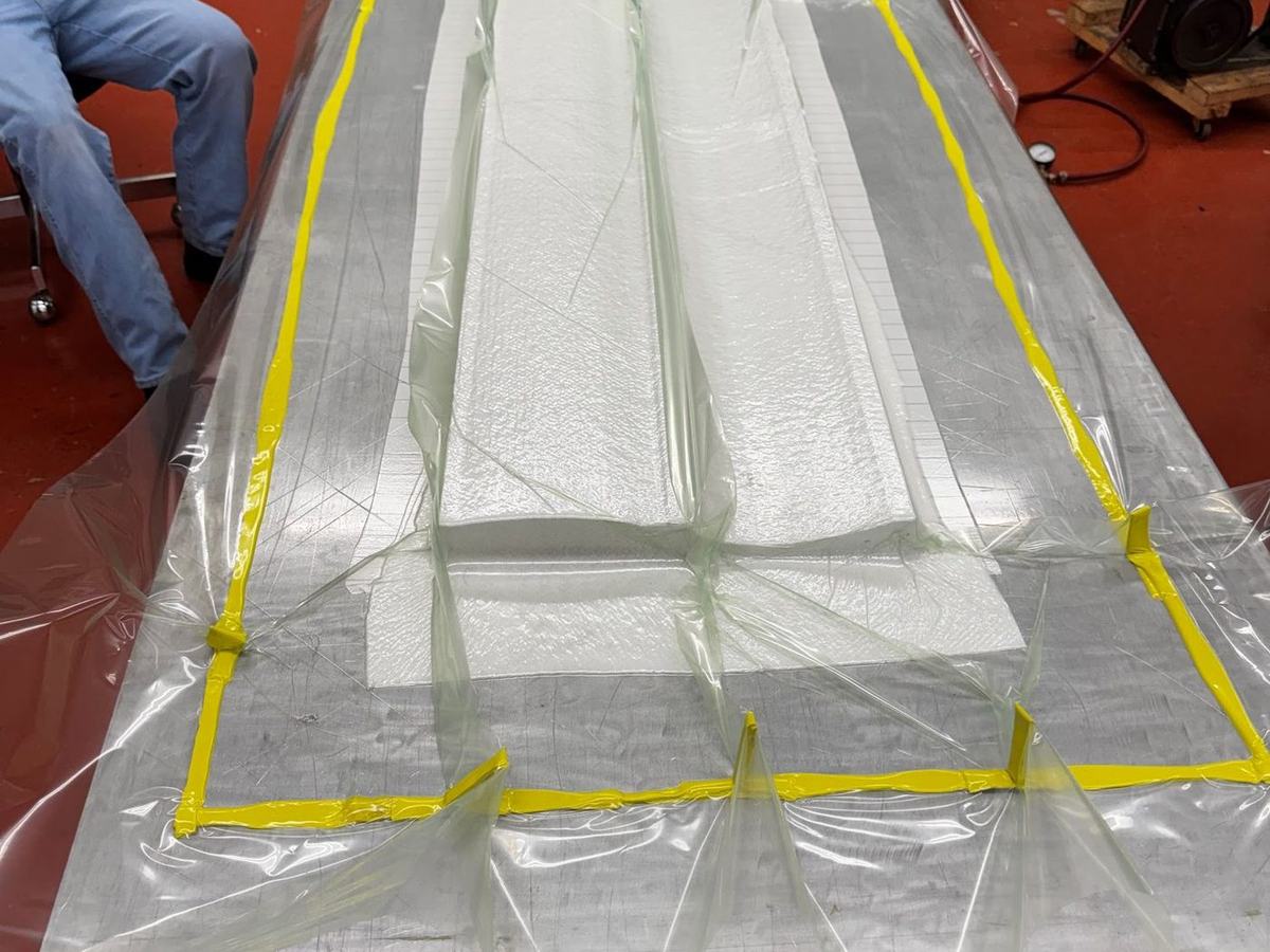
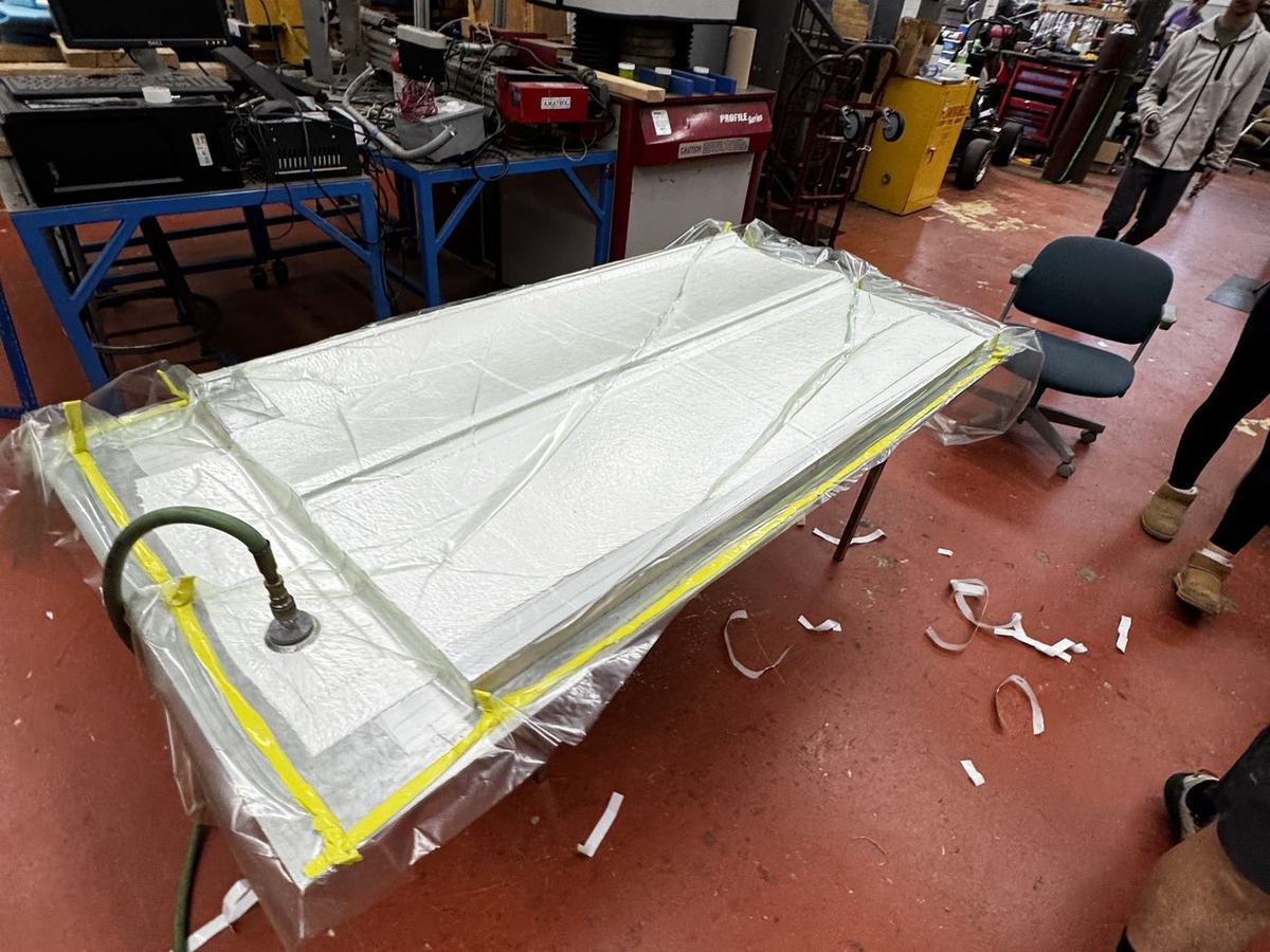
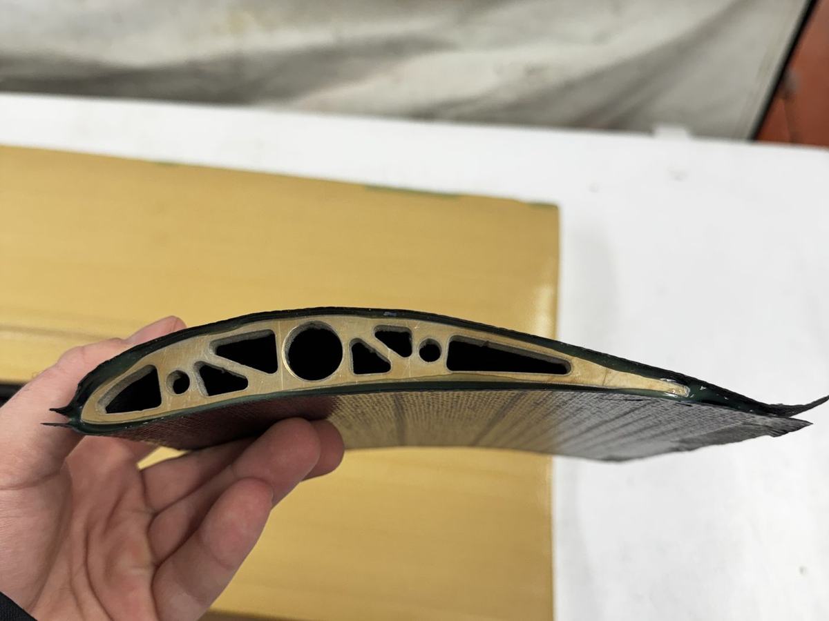
Prepreg carries resin at a controlled ratio, which keeps fiber volume high and mass low. We built a cut plan and ply templates to use the material efficiently and cut every ply at once, reducing both waste and storage. Skins ran two plies — outer at ±45° to resist crack propagation from cone strikes, inner at 0°/90° for stiffness — with glue film bonding carbon skins to foam cores on endplates and ribs.
Bagged parts were leak-checked before every cure. The team's oven was serviced first: heating elements and insulation improved, temperature tracked closely. Laminates reached about 250 °F, held through the bake, then ramped down overnight to keep the molds from warping. Parts released cleanly with a smooth surface and a straight trailing edge.
Mounting & Internal Structure
Mounting is where a first-year aero package usually gets rejected, so this carried the most design scrutiny.
Front wing
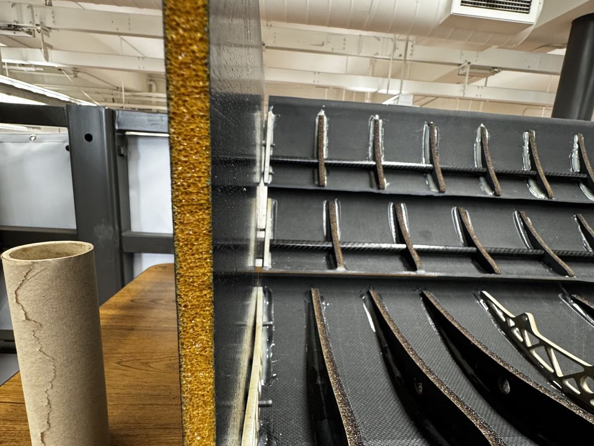
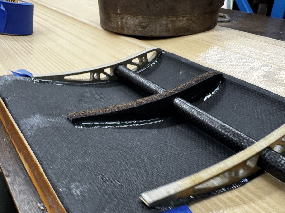
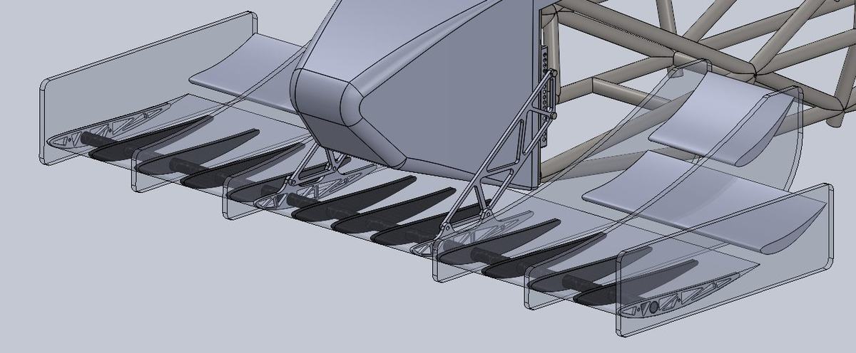
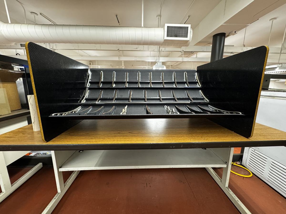
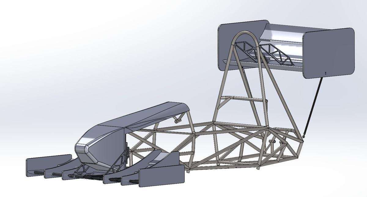
Two aluminum dovetail blocks tie the wing to the chassis at two points, landing on reinforced tabs built into the airfoil. Internally the wing runs a carbon fiber tube spar with carbon-foam ribs, which resists bending while keeping the skin stable against torsion and shear. Front mounts were positioned relative to the front bulkhead so that an overload fails in shear rather than buckling.
Rear wing
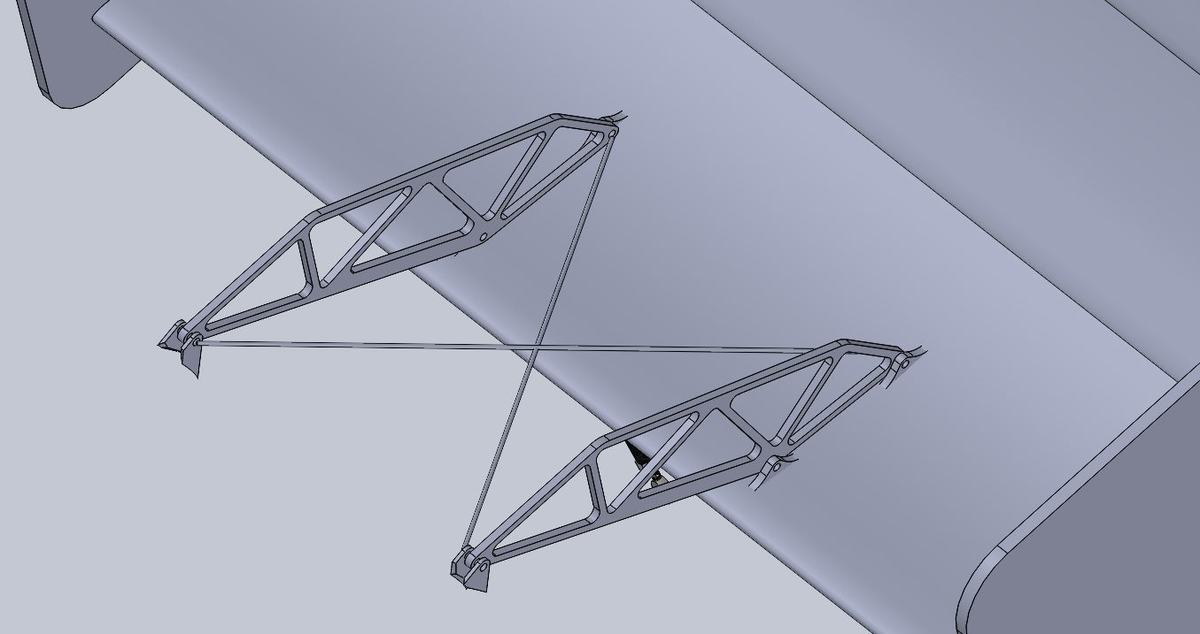
Rules require the rear mount to be rotationally free, so it has a single chassis connection — a light swan neck landing on an internal aluminum rib near the center. Two straight carbon rods at the endplates carry vertical load in tension and compression, and crossed tension cables between the swan neck mounts take lateral and inertial load through cornering. Low mass, stable structure, and the cable pretension is adjustable.
FEA concentrated on the three places most likely to fail: the swan neck shear point, the bearing and shear at the internal aluminum rib, and the front mounts under cone impact — the highest load case that hardware will ever see. Deflection simulations on the skins set internal rib spacing. Results drove hardware sizing, skin reinforcement patches, and rib thickness.
Validation
An endplate trial — half-inch foam core, two prepreg plies per side, glue film between core and skins — was loaded on a bench with half the plate cantilevered off a table. It held roughly 200 lb without failure, comfortably more than needed, which meant thickness and ply count could come back down to save mass while still meeting the impact case.
Beyond bench work, we built an adapter plate so the wings could be mounted to a test stand and load-tested before ever going on the car, and planned strain gauge instrumentation to measure real downforce during runs and correlate it against the CFD predictions. As one of the team's drivers, and the only member of the four-person aero group with vehicle dynamics experience, I translated that test data into predicted vehicle response and fed it into the aero balance targets — biased toward mild oversteer given the chassis. Our team captain also brought strong dynamics knowledge and held final say on balance.
Outcome
The package was finished past the end of the course. I kept working through the remaining layups, mounting hardware, and surface finishing to get it competition-ready.
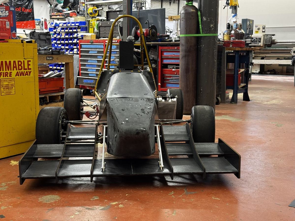
It ran at Formula SAE Michigan, passed technical inspection, and survived the full event with measured lap-time gains — the first aerodynamic package in the program's history, and a documented process the team can repeat.
The economics are worth stating plainly: the club sells nothing, so the package returns no money. The return is lap time and competition points. Against a $1,750 allocation and a roughly $3,550 scope, the gap was closed by donated material from the composites lab and the Mountaintop makerspace, a repeatable split-mold process, pre-cut ply layouts that minimized waste, and standard stock for the mounts.
What I'd Do Differently
- Write the post processor first. Machining time was gated by a toolpath limitation, not by the design — and that was solvable weeks earlier than we solved it.
- Soften the toolpath profile changes and raise feed, spindle speed, and stepover together; the tooling foam cuts cleaner fast than slow.
- Trim the endplate laminate. Holding 200 lb when the requirement is far lower is mass we carried for no reason.
- Get the downforce test rig built earlier so simulation correlation informs the design rather than confirming it.