- Measure
- →
- CAD
- →
- FEA
- →
- Fabricate
- →
- Install
- →
- Field Test
- Platform
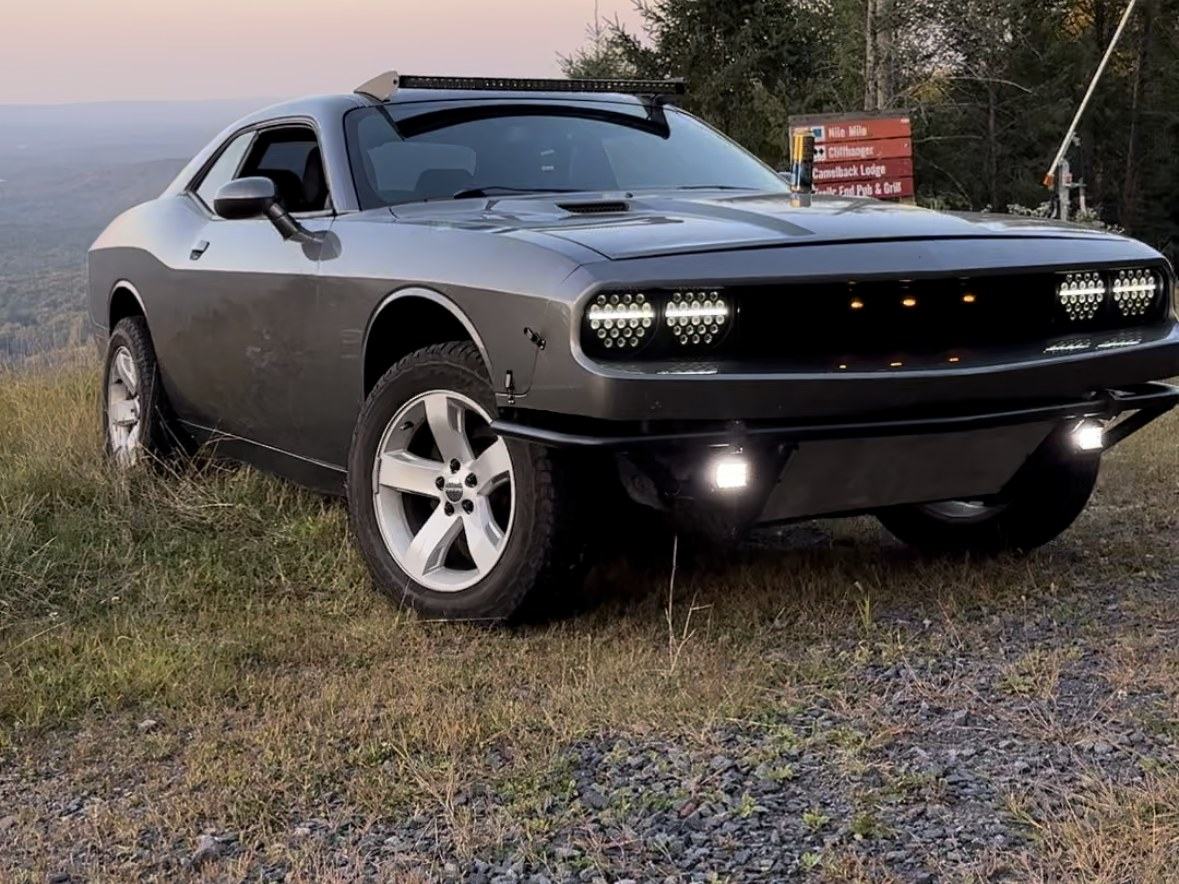
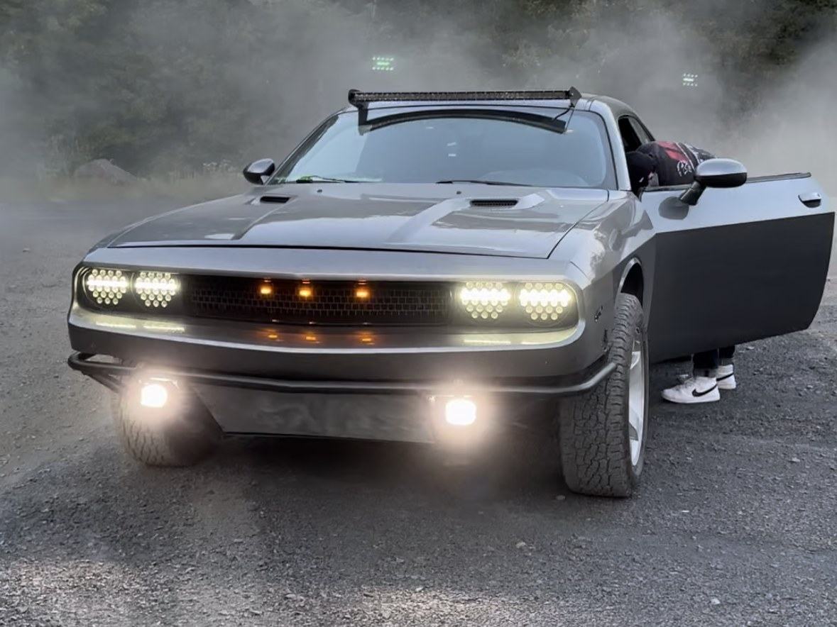
- 2012 Dodge Challenger RT
- Role
- Solo — design through fabrication
- Materials
- Plate and tube steel, aluminum
- Validation
- Off-road use and annual cross-country mileage
The Platform
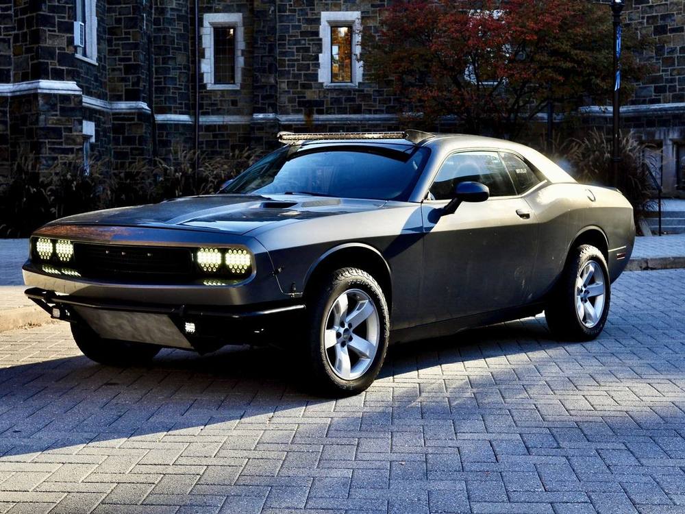
A 2012 Dodge Challenger RT is not an off-road vehicle and nobody makes parts to turn it into one. That is the reason I chose it. With no aftermarket catalogue and no factory reference geometry to build from, every bracket on the car is an original design problem — measured off the vehicle, modeled, analyzed, fabricated, and then proven by driving it.
Roof Rack
Almost all of the design work here went into mounting the rack, not the rack. Building the rack itself was never the hard part — attaching anything to this roof was.
Why nothing off the shelf works
A Challenger was never meant to carry a roof rack. What exists on the market is suction cup and magnet systems, and those are fine for a highway trip to a ski resort. They are not fine for the terrain this car sees. Holding a loaded rack to a painted roof panel by suction over rough ground, for days at a time, is not a system I was willing to trust.
Iteration one: drill the seam
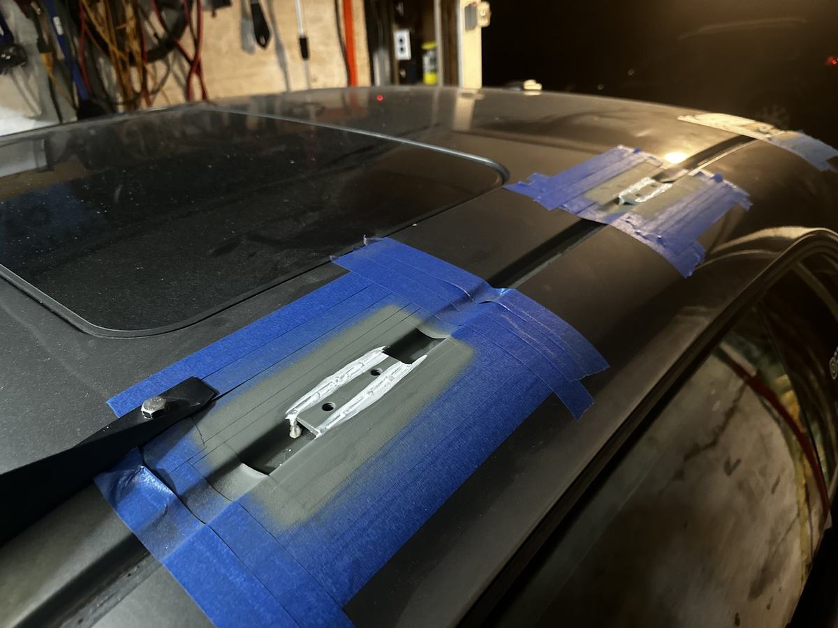
The first design bolted brackets through the rain gutter, where the roof panel and the body side are spot welded together — the strongest area on the roof. I measured the curvature, designed the brackets around it, and fabricated them.
Installation failed immediately. No drill bit I had would cut it. I had assumed the whole seam was mild steel, because the roof and the body side both are. What is actually in there is a hardened steel core sandwiched between them as part of the crash structure. The assumption was wrong, and the only way to find that out was to try to drill it.
Iteration two: a clamping system
Next I tried to design something consumer-facing — a clamp that expanded inside the rain gutter channel, requiring no permanent modification. Every version I drew had the same failure. The geometry constrains beautifully in the lateral directions and nothing constrains it vertically. A rack that cannot resist being lifted is not a rack.
Iteration three: build the surface that should exist
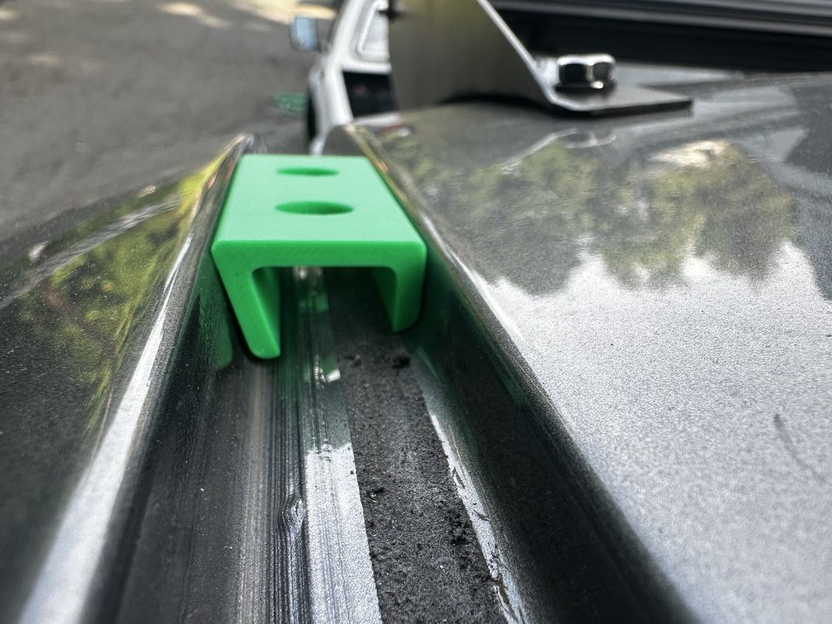
So I changed the premise. Anyone modifying a car this heavily for off-road use is not looking for a reversible accessory — they want it to work. That freed me to design a permanent mounting surface in the rain gutter, the same feature most trucks, SUVs, and older sedans already have from the factory.
The bracket was sized in CAD to distribute applied load rather than concentrate it, and its underside had to match the rain gutter's real geometry. I captured that with a profile gauge and verified it with iterative 3D-printed prototypes until the fit was right.
From welded to milled
First production attempt was waterjet-cut parts, TIG welded into assemblies. That failed on precision. The brackets sit at specific angles in the gutter and all six need a common reference to a flat, level plane — if one sits a degree off, the rack does not. Weld distortion moved them too much.
So I dropped the weldment entirely, wrote a toolpath, and had the brackets milled from solid mild steel. One operation, no heat, no distortion.
Installation, and the real failure mode
Attaching them exposed the thing that actually governs this design. The car's sheet metal is very thin, which means the brackets were never going to be the weak link — the failure would be the sheet metal shearing around the welds.
That ruled out laying down heavy weld. Instead I ran a series of tack welds around the perimeter of each bracket: maximum bonded surface area, minimum heat into the panel. Too much heat warps the roof, embrittles the sheet metal, and re-tempers the hardened crash structure underneath — the same structure that stopped my drill bit in iteration one.
Installation was a balancing act between coverage and heat input, and all six brackets went on successfully. They sit flush in the gutter, and with the original rain gutter guard reinstalled they disappear into the car.
The rack, and the trip
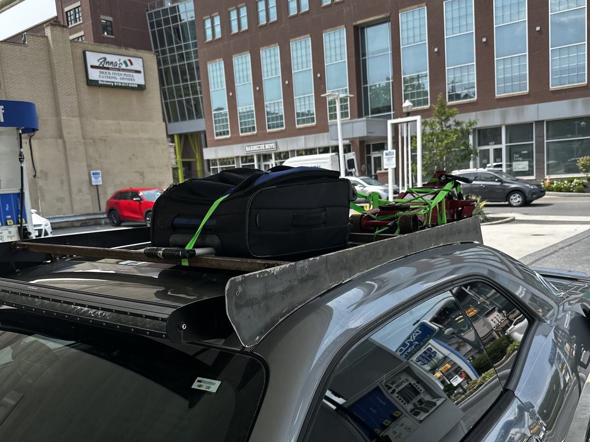
With mounts that worked, the rack came together quickly: plasma-cut 1/8 in steel and welded box tubing, finished in time for a cross-country drive.
It went out fully loaded — tools, a spare tire and wheel, and the car jack — and the whole system held for the five-day trip. The moonroof still opens and closes exactly as it did from the factory.
Paint and the plastic covers that will protect the brackets are still to come. They are functional and strong as they are.
Front Bumper
The bumper had to satisfy two requirements that pull against each other. It needed to take an off-road impact, and it could not compromise a car that still gets driven every day.
Designed load path
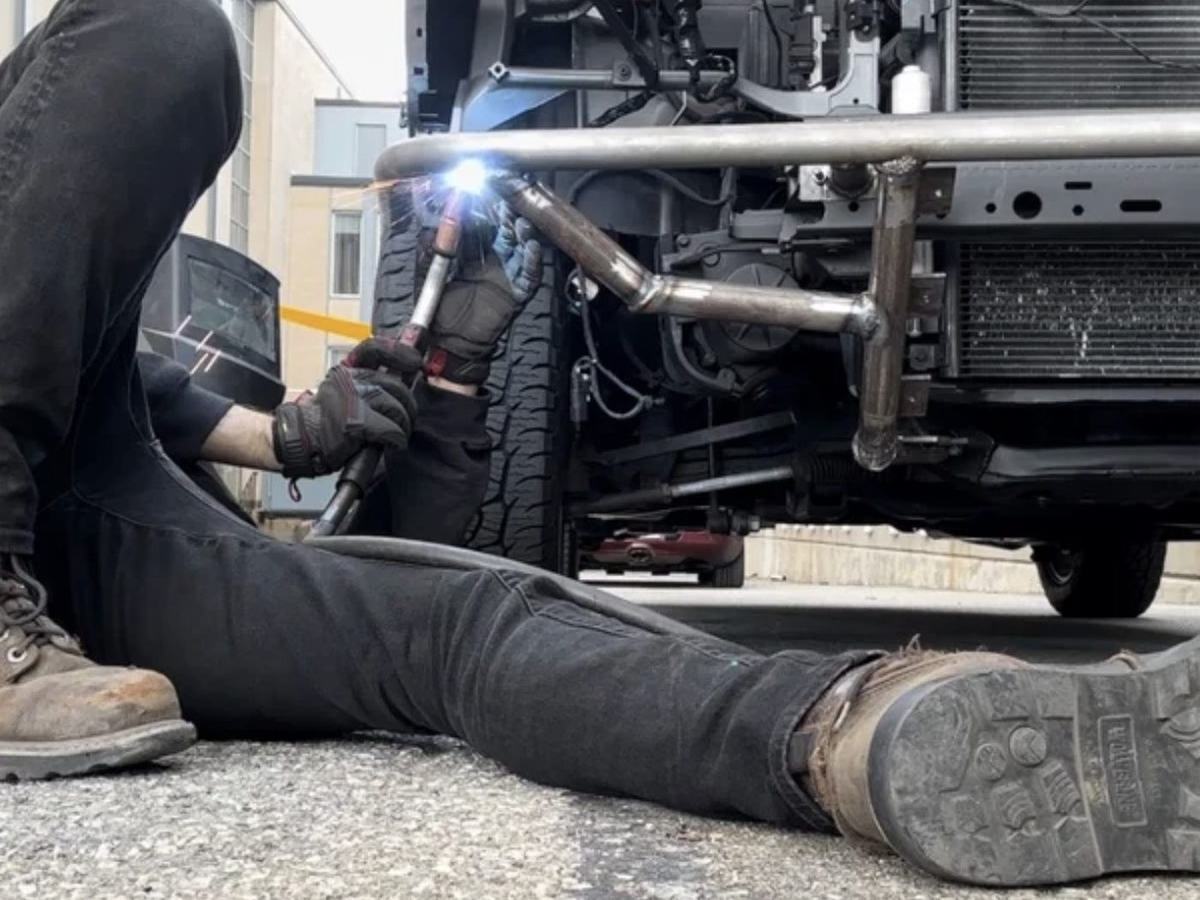
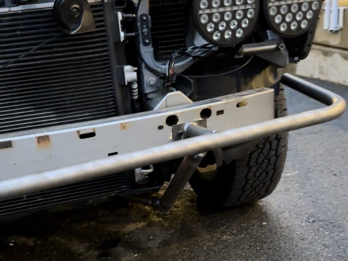
The main impact structure is 1.5 in DOM steel tubing, chosen for the highest strength available in that size because it is the surface that actually takes the hit. The tubes tying that structure back to the subframe are also 1.5 in, but thinner-wall and deliberately not DOM — lower strength on purpose, so that in a serious impact they deflect rather than transmitting the full load straight into the chassis.
That distinction is the whole design. The factory crash structure is engineered to absorb energy in a specific way, and a rigid steel bumper welded across the front of it would defeat that. This bumper is an addition to the crash structure, not a replacement for it: strong where it meets the obstacle, intentionally compliant where it meets the car.
Removable by design
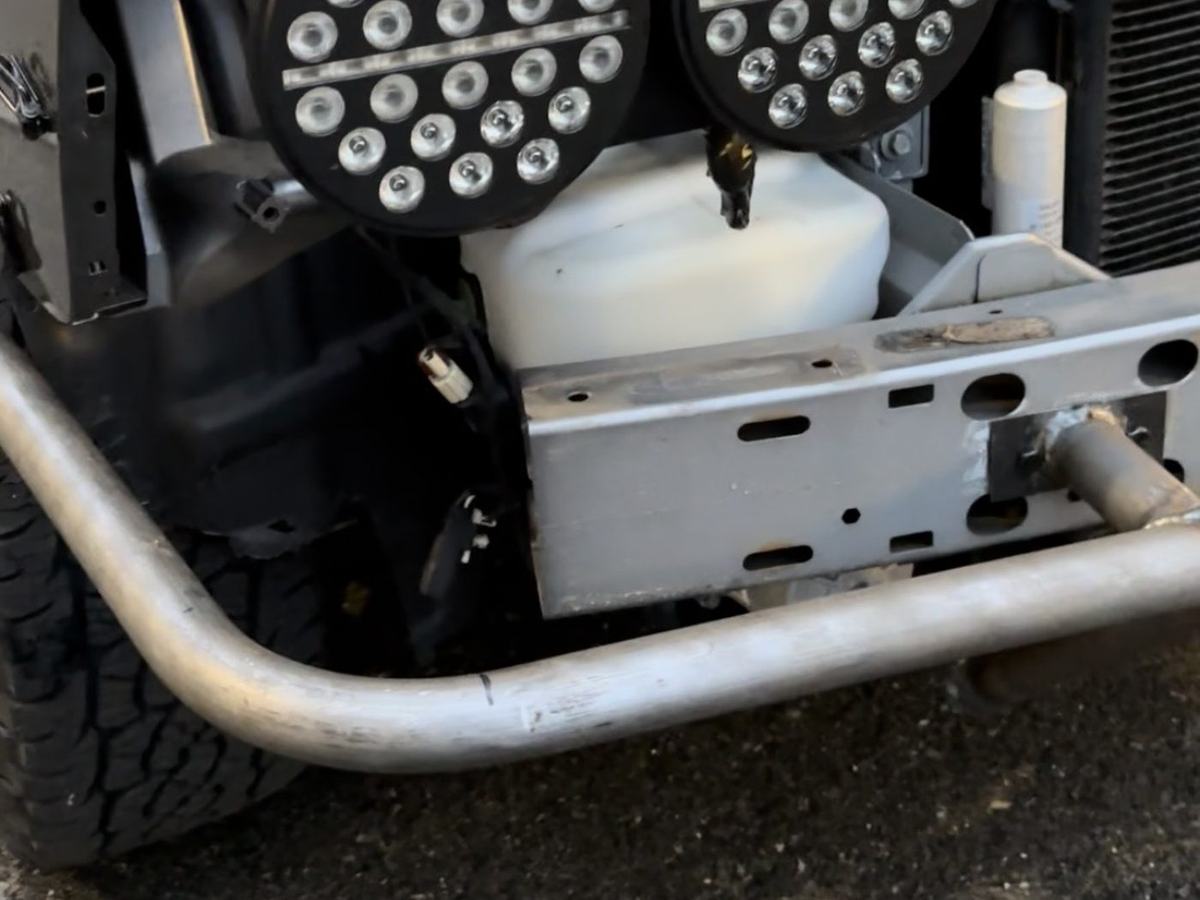
This was my first part designed for someone other than me, and that changed how I approached it. Nothing is welded to the vehicle — the bumper bolts on, and it comes off. A part that permanently modifies a customer's car is a different product from one that does not, and I wanted this to be the second kind.
The car was never meant to carry a bumper like this, so fitting it still requires modification: cutting the front plastic fascia, raising the radiator two inches by modifying its bracket, clearancing the hood latch, and relocating the horns. Every one of those is reversible. The car can be returned to stock.
Radiator relocation
On a stock Challenger the radiator is the lowest point on the car. Anything you hit, you hit the radiator with first. Moving it up two inches was not a packaging workaround to make room for the bumper — it was the point. Ground clearance at the front of the car is set by the most fragile component on it.
That reasoning led to one more part: a bolt-on aluminum section across the front of the bumper that shields the face of the radiator and the AC condenser, and closes off the underside against direct impact from below.
Since installation
Strength has been proven off-road in dirt and snow, and in parking lots by other people reversing into it. The bumper has not flinched.
Lighting
Stock lighting is built for pavement. Running dirt at night needs more light and more spread, and none of the parts that would give you that exist for this car.
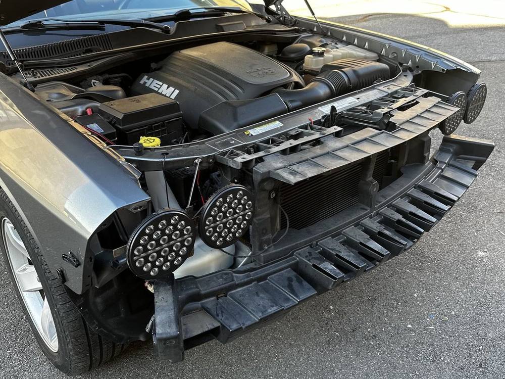
Fog light pods
The simplest of the three. Pod lights wired into the existing fog light harness, so they run off a circuit the car already has and switch the way the factory fogs did.
Headlight conversion
The headlights are now four Jeep units, two per side. Getting them onto the car took two things that did not exist.
First the electrical: Jeep headlights terminate in a three-prong plug and the Challenger expects a six-pin coupler. I built a custom harness to convert between them, so the lights run off the factory wiring with no cutting into the car's loom.
Then the mounting: a custom bracket that positions the Jeep units in the stock headlight location and picks up the original factory headlight mounting points. Nothing was drilled or modified to fit them — the stock headlights can go back in.
Roof light bar
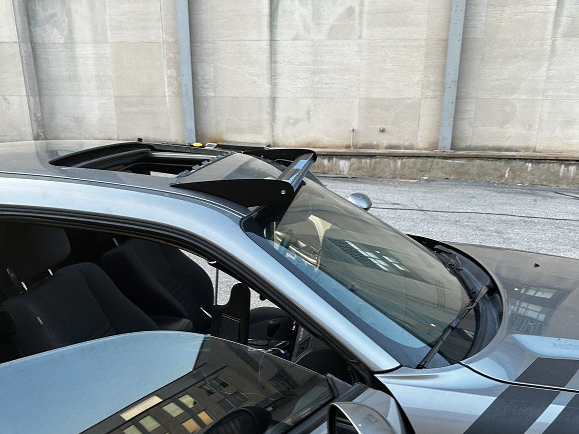
The bar itself is an off-the-shelf straight LED unit. The mounts are entirely mine, because roof light bar mounts for a Challenger do not exist. It is not that they are expensive or hard to find. Nobody makes them.
The roof is a compound curve, so the first problem was capturing a shape I had no drawing for:
- Took a contour gauge to the roof to capture the actual curvature.
- Modeled that geometry in CAD, and designed the bracket around it.
- Waterjet the parts from sheet metal.
- Used a roll bender to form the bottom foot of each bracket to the roof's curvature so it sits flush rather than point-loading the panel.
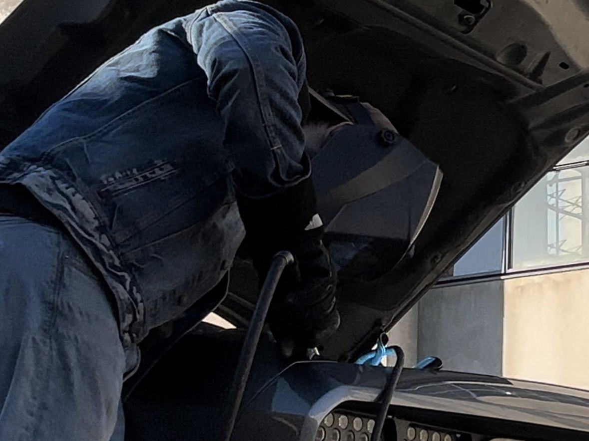
- TIG welded the brackets up.
Then the part that makes it a daily driver problem rather than a fabrication one. Mounting means six holes in the roof, directly above the cabin. Each hole got a threaded rivnut set with silicone sealer, and the brackets bolt to those with Teflon tape on the threads — two independent seals at every penetration. A roof leak on a car you drive every day is not an acceptable outcome, and the fastener choice is doing as much work as the bracket geometry.
Suspension & Ride Height
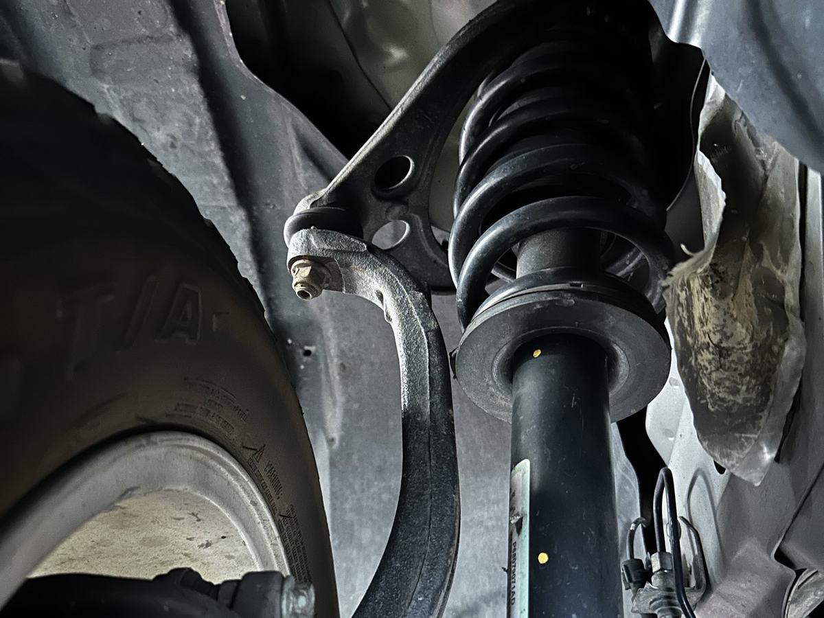
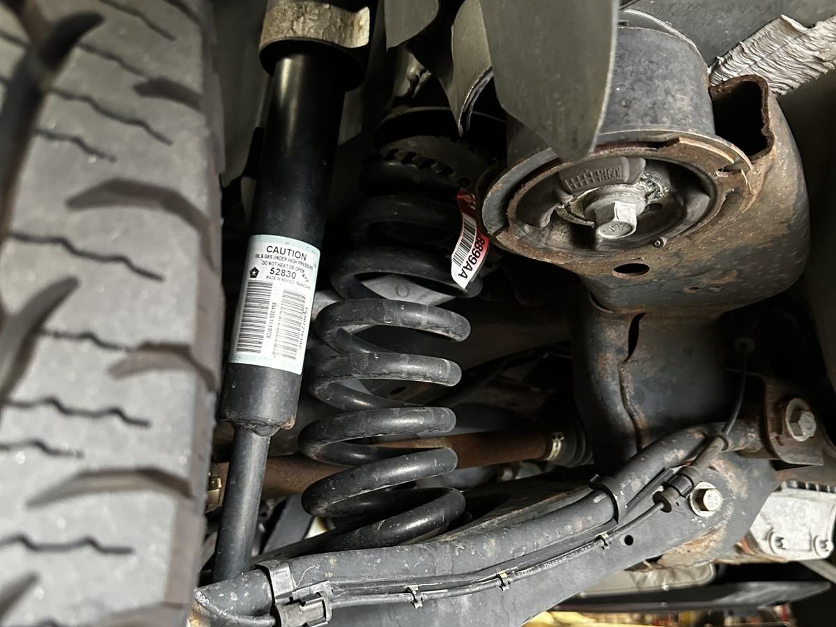
I designed and fabricated the lift spacers to get the ride height the build needed. Raising a strut platform does change suspension geometry, and correcting that properly would have required custom control arms, which were not in scope. I went in having decided the ride height was worth the geometry change.
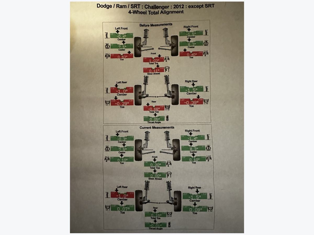
The alignment sheet shows exactly what the lift cost. Toe came back fully into specification at all four corners — front total toe from 1.03° to 0.20°, rear total toe from −0.68° to 0.16°, thrust angle to −0.01°. Caster was unaffected at 7.5° and 8.3°.
Camber is what the lift actually costs. It sits outside factory spec at three corners and stays there, because correcting it on this platform needs adjustable hardware the car does not have. That is the trade I accepted going in — and having the numbers in front of me meant I knew precisely what it cost instead of guessing.
A related design study sits alongside this: long-travel control arms, sized from hand-calculated motion dynamics for an advanced dynamics course. The upper arm cleared its factor of safety comfortably even in small tubing, so it never became the constraint — FEA in SolidWorks concentrated on the lower arm, which carries the loading that matters, and that analysis drove a plate-steel section over tube. They are designed, not fabricated; the car still runs its factory arms.
Chassis & Exhaust
A rear strut brace, and a NASCAR-style boom tube exhaust built because I wanted to hear it, not because it does anything for the off-road brief. Each part is a small design job with the same constraint: no reference geometry, so everything begins with measurement.
Not everything on a build has to justify itself against a requirement. Some of the best ideas on this car came out of work I did purely because I enjoyed doing it — keeping that in a project is what leaves room for the creative solutions to show up.
Failure Analysis
The driveshaft center support bracket failed twice. The first time I replaced it with a stock part, and it failed again — which is the useful signal: if the same part fails the same way twice, the part is not the problem.
Tracing it properly turned up heat and driveline angle fatigue as the root cause. I started designing a billet replacement, but the better answer was to treat the cause rather than the symptom — reworking the exhaust routing to manage the heat load on that area. Fixing the environment the part lives in solved it, where a stronger bracket would only have delayed the next failure.
Validation
Every fabricated component gets proven the same way: mild off-road use, then an annual cross-country drive with the newly fabricated parts installed. A few thousand miles of real road and real load finds things a simulation will not, and it is an honest test because failure is inconvenient in a way that matters.