- Packaging
- →
- 3D Sketch
- →
- Weldments
- →
- CG Balance
- →
- Design for Shop
- Engine
- Honda GX390
- Tools
- SolidWorks weldments, 3D sketches
- Constraint
- No precision bender; scrap stock
- Status
- Design complete, not yet fabricated
The Brief
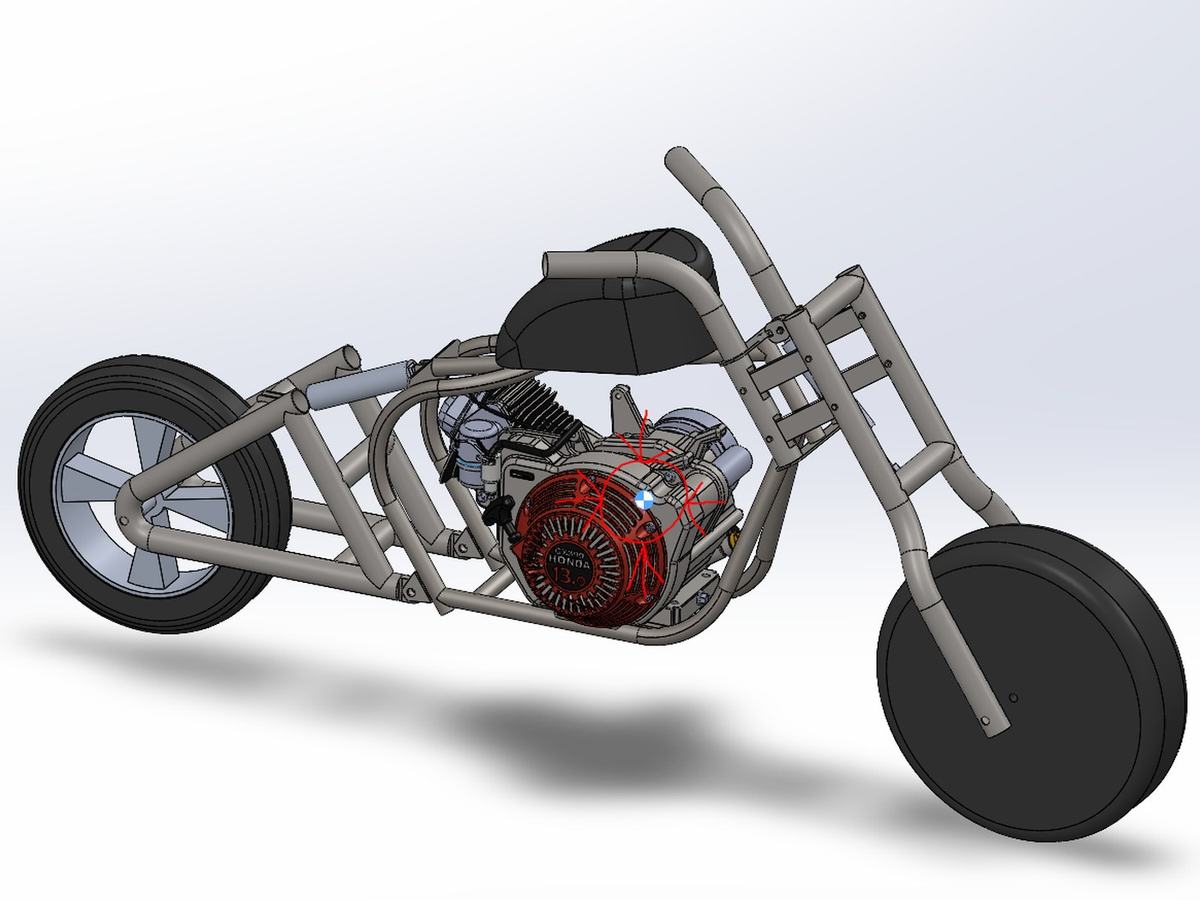
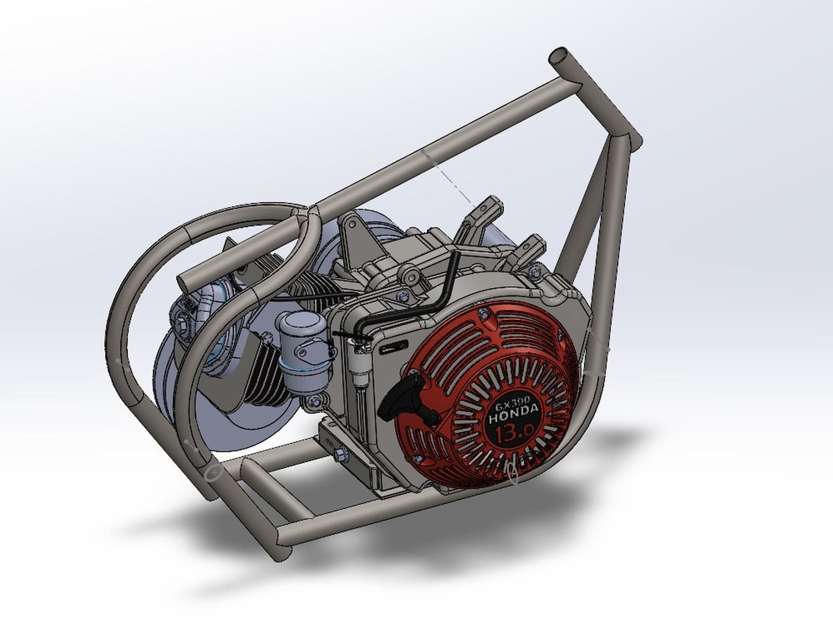
A self-set design test: build a tubular minibike chassis around a Honda GX390 and see whether I could hold the design together under constraints I set deliberately tight. A minibike should be small. A GX390 is not. The two requirements fight each other from the first sketch.
I also wanted it to go off-road, which meant cutting the chassis down far enough to leave real travel for the front fork and the rear swingarm. Every tube placement ended up trading against something else — engine clearance, suspension travel, rider position, or the ability to actually weld the joint.
CAD Approach
Built in SolidWorks using weldments and 3D sketches, which is the right toolset for a tube chassis and a step up from modeling parts individually. The frame is driven by a 3D sketch skeleton, so moving a node updates the structure instead of forcing a rebuild.
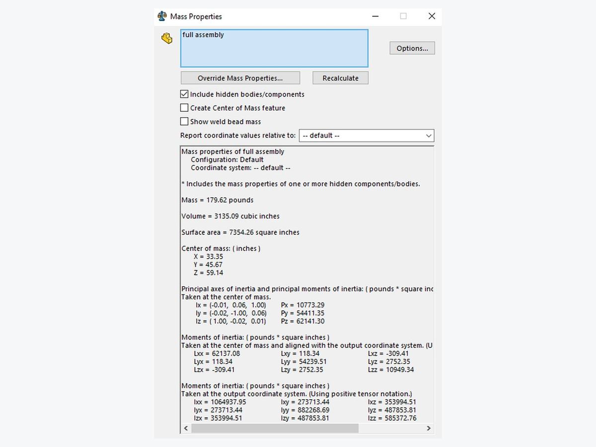
Center of gravity was the part I most wanted to get right in-model rather than discover on the first ride. By assigning real material properties to every component, mass distribution came out of the assembly directly — so CG placement became something I could design toward and iterate on rather than estimate.
The full assembly comes out at 179.6 lb, with the center of mass and the principal axes of inertia solved from the model. Moving a tube and watching the CG move with it is the whole reason for building it this way.
Designing for the Shop I Actually Have
This is the constraint that shaped the whole frame. I do not own a precision tube bender, which means I cannot reliably produce two identical bends. A design full of mirrored bent tubes would be undrawable for me in practice, however good it looked in CAD.
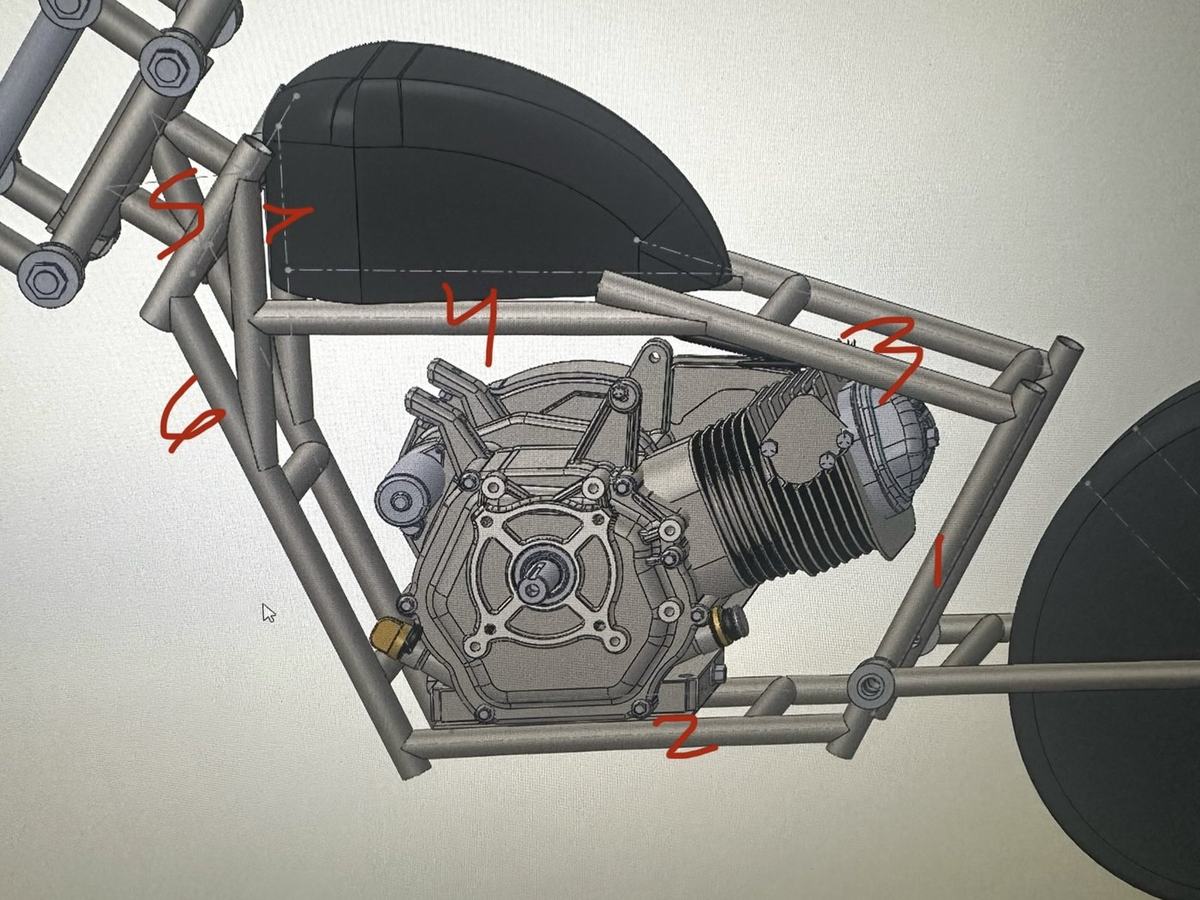
So the first version eliminated bending entirely. Every corner became a notched joint, tubes cut to meet each other instead of curving around. It has more parts and it looks more complicated, but that was the point: given the tools I had, it was the most accurate frame I could actually build. Accuracy was the thing I could control, so the design was shaped around it.
The cost is structural. Every notch removes material exactly where the joint carries load, and a frame with that many of them is weaker than it needs to be. Accuracy had been bought with strength.
Rather than accept the trade, I changed what I was capable of. Once I had built tooling that made bends repeatable, the current frame could use bent tubes wherever a bend beats a joint — continuous material through the corner, fewer welds, fewer stress risers. The equipment gap did not disappear; I moved it somewhere I could solve it.
Notching without a notcher
Notched joints are only easy if you own a tube notcher. I do not, and a hole saw will not reliably produce two identical notches — which is the same repeatability problem the bends have, in a different form.
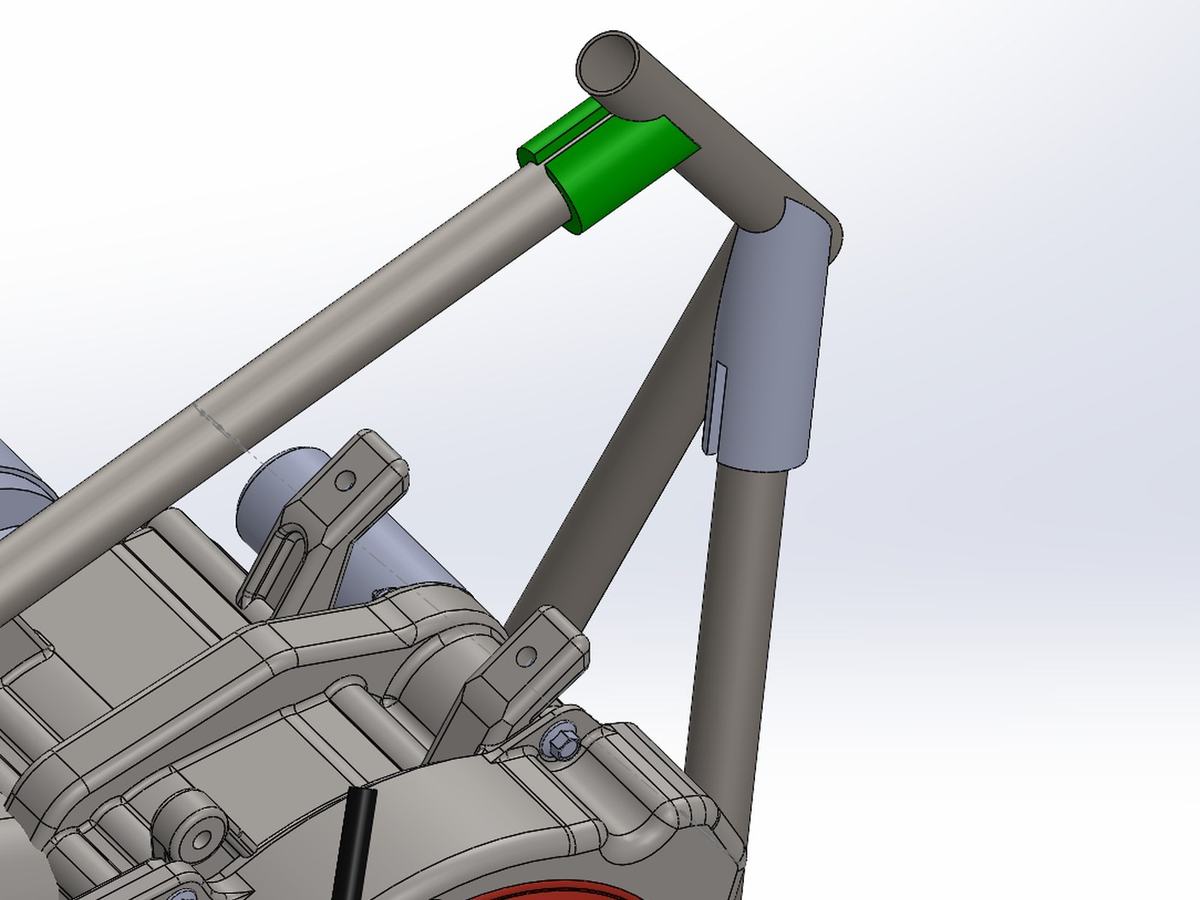
So I modeled notch sleeves in CAD and 3D printed them. Each sleeve slips onto the tube and seats in exactly one position, and its edge is the profile of the cut. Trace around it and the notch is marked correctly, in the right place, at the right clocking — every time, on every tube.
It moves the precision from the cut into the model, which is where I actually have control. The later frame revisions were adjusted specifically to make these sleeves work.
Custom Bend Measurement Tooling
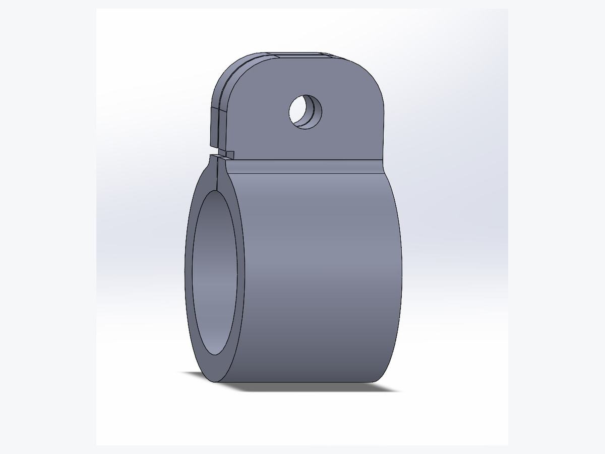
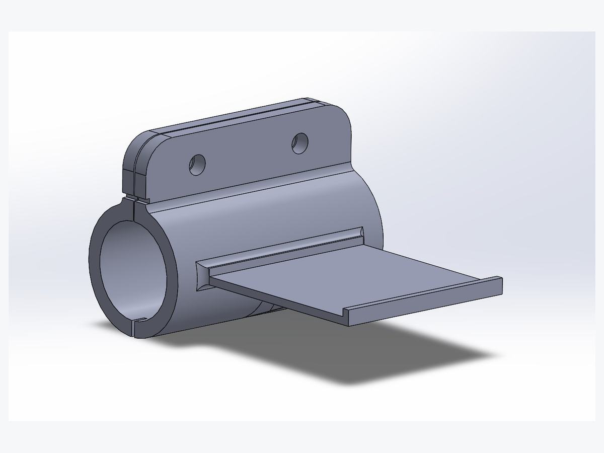
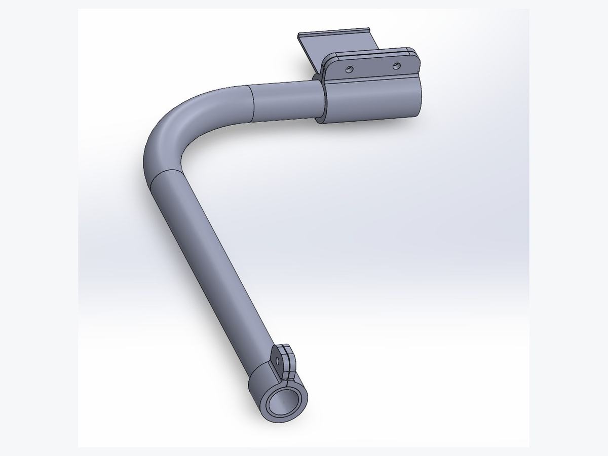
Repeatable bends still need to be measured, so I designed tooling to do it. It is two parts that clamp to the tube and work together.
- The position locator is the smaller clamp. It fixes a reference point on the tube so every measurement is taken from the same place rather than from wherever the tape happens to land.
- The end locator is the larger part, carrying a flat machined face that an angle gauge sits against — so degrees of bend can be read directly off the tube instead of estimated.
Both parts carry a notch, and measuring notch to notch gives the distance between the two reference points. Together the tooling captures end-to-end distance, levelness of the tube through the bend, and degrees of bend while the bend is happening. That turns a feel-based operation into a measured one, and it is what makes a second identical tube possible without buying a machine.
Suspension
The rear is a conventional setup, the kind you would find on a cafe racer. The front is not, and the reason is cost.
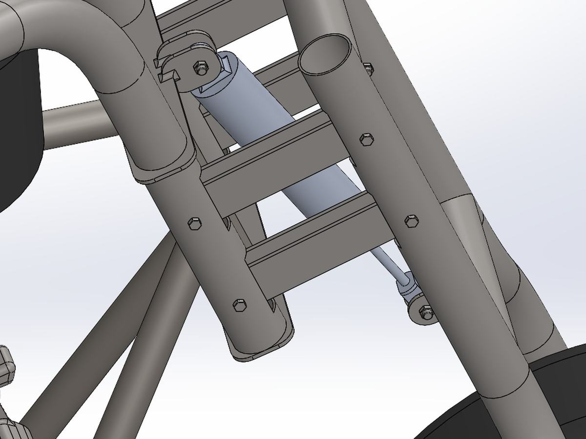
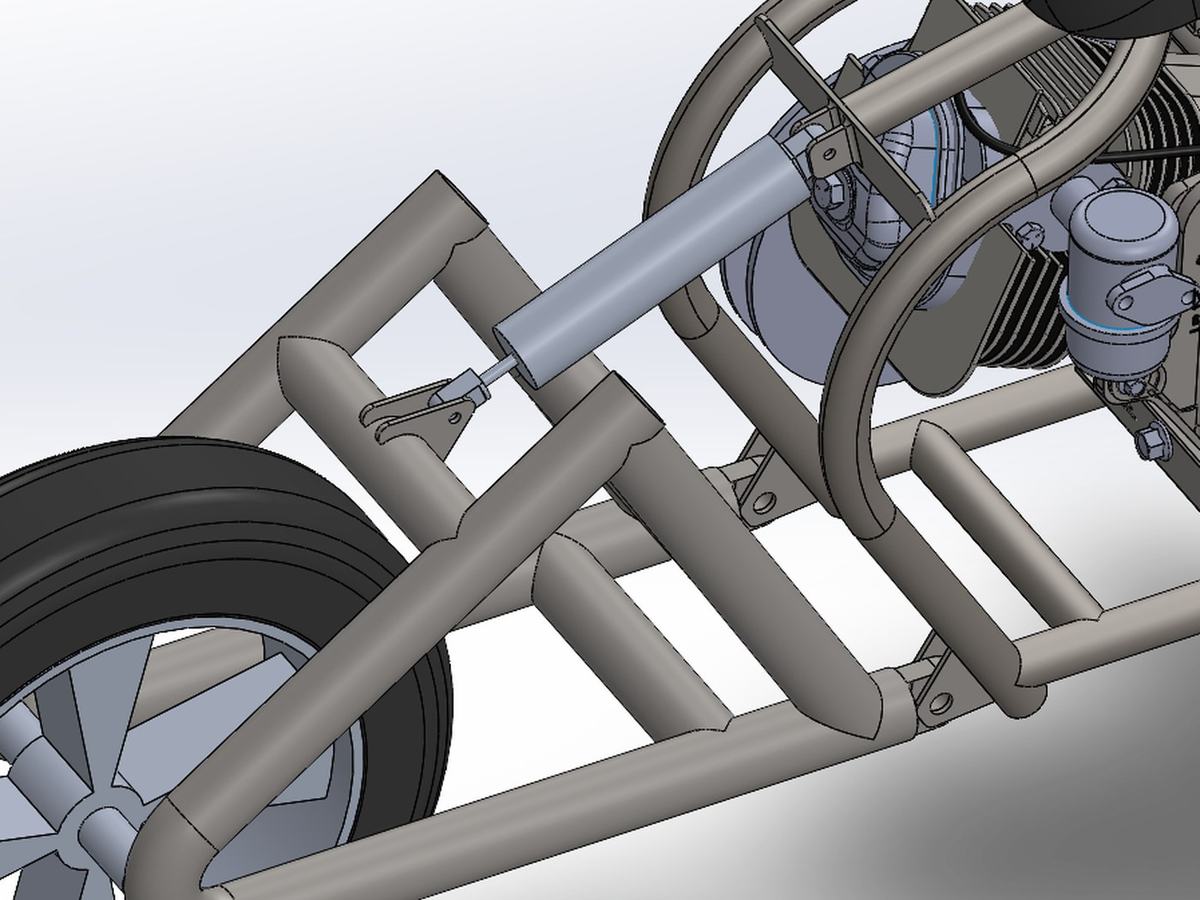
A complete dirt bike front fork assembly is expensive and awkward to source. A coilover shock on its own is cheap and available anywhere. So the front runs an almost four-link arrangement with a single coilover — geometry I can fabricate myself, built around the one component I actually have to buy.
That is the same trade as the bend tooling, pointed at cost instead of accuracy: manufacturing capability converts directly into money saved. If you can make the linkage, the purchase price of the front end collapses from a whole fork system down to a single shock.
Materials & Cost
Scoped from the start to be buildable out of scrap and second-hand stock. That is a design constraint, not a footnote: it pushes toward common tube sizes, standard fasteners, and geometry that tolerates whatever length of material actually turns up.
Status
The design is complete in CAD. It has not been fabricated yet — this was a skill test first, and it did what I wanted it to: it forced me into weldments, 3D sketches, and mass-properties-driven CG work, and it made me design against my own shop's real capability rather than an imaginary one.